´Ó±ê×¼¿´¿´ÎÒÃǶÔÓÚAES3 µÄÁ¬½ÓÎóÇø
SREXACT
SREXACT ̨ž³ÈÕ•NëŠ×Ó Œ£˜IÎę̀Ÿô¹âÒôîl¾€À|ßB½ÓÆ÷ ÕûówßB½Ó·½°¸ÌṩÉÌ
ÒÔÏÂÄÚÈÝת×ÔÖªÃų̂ÍåÏßÀÂÉú²úÉĮ̀ÍåÈÕÉýµç×ӵĹ«ÖÚºÅSREXACT£¬×÷ÕßÊÇ»ÆÓ¢ÕÜ¡£°¢ÕÜÀÏʦÊÇ̨ÍåÖªÃûÒôÏ칤³Ìʦ£¬´ÓÊÂÒôÏìÐÐÒµ½ü20Ä꣬¶ÔÐÐÒµÓкܶà¶Àµ½µÄ¼û½â¡£¸Ã¹«ÖÚºÅÉϺܶà¹ØÓÚÏ߲ĺÍÁ¬½ÓµÄ¼¼Êõ¸É»õ¾ù³ö×ÔËûµÄÊֱʡ£

¿´µã:
AES3 ¾ÓÈ»²»ÓÃÔÚÒâÐźŵÄÀäÈȶË
AES3 ¿ÉÒÔ´«¶àÔ¶?
ÕýÎÄ¿ªÊ¼
ÔÚÒôƵÐÐÒµÖÐÏà¹Ø±ê×¼µÄÖƶ¨Õß»ù±¾ÉÏÓм¸´ó×éÖ¯:
TIA ITU Ö÷Òª»ùÓÚͨÐÅÐèÒª×ö±ê×¼½¨Á¢
AES ÒÔרҵÒôƵΪÖ÷
EBU ÒÔµçÊÓ/µçÓ°ÅäÌ×µÄÒôƵ±ê׼ΪÖ÷
IEC ¹ú¼Êµç¹¤Î¯Ô±»á
ÄÇ̸µ½Êý×ÖÒôƵ±ê×¼×î×îÖØÒªµÄ±ê×¼Ó¦¸Ã¾ÍÊÇ AES3ÁË
Õâ¸öAES3±ê×¼ÔÚÎÒÃÇÁ¬½ÓÐÐÒµµ±ÖеÄÖ¸µ¼±ê×¼±»Ð´ÔÚ
AES3-4-2009(reaffirmed 2019)
ÓÃÓÚÊý×ÖÒôƵµÄAES±ê×¼¡ªÊý×ÖÊäÈëÊä³ö½Ó¿Ú-
Á½ÐŵÀ´®Ðд«Êä¸ñʽÏßÐÔ±íʾµÄÊý×ÖÒôƵÊý¾Ý-µÚ4²¿·Ö:ÎïÀíºÍµçÆø
AES standard for digital audio ¡ª Digitalinput-output interfacing ¡ª
Serial transmission format for two-channellinearly represented digital audio data
Part 4: Physical and electrical
(Multi-part revision of AES3-2003,incorporating Amendments 5 & 6)

¹ØÓÚÁ¬½Ó±»Ð´ÔÚ¸½¼þC£¨¹æ·¶ÐÔÎļþ£©Æ½ºâ´«Êäµ±ÖÐ
ÏÂÃæÎÒÃǾʹø×Å´ó¼Òä¯ÀÀһЩÖصã°É£¡
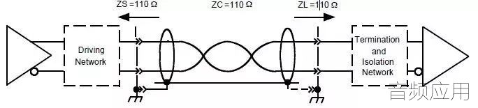
ÕâÕÅͼÉÏÃæÎÒÃÇ¿ÉÒÔ¿´µ½¼¸¸öÁÁµã:
£±£® ·¢ËͶ˱ØÐë½ÓµØ¶ø½ÓÊÕ¶ËÊÇÐéÏß¿ÉÒÔÑ¡ÔñÐÔµÄÁ¬½Ó
£²£® ´«ÊäÏßÊǶԽÊÏß
£³£®·¢ËͶËÏß½ÓÊն˶¼ÊÇ110 ¦¸
NOTE The electrical parameters of the interface are based on those defined in ITU-T
recommendation V.11 which allow transmission of balanced-voltage digital signals over cables
up to a few hundred meters in length.
×¢ÊÍÌáµ½ÁË: ÕâÑùµÄ´«Ê䷽ʽÔÊÐíÔÚ³¤´ï¼¸°ÙÃ׵ĵçÀÂÉÏ´«ÊäƽºâµçѹÊý×ÖÐźš£
ËùÒÔÎÒÃDzâÊÔÏßÀÂAES3´«ÊäÄÜÁ¦Ôڵ͵çÈݲÄÁÏÉÏÔø¾ÑéÖ¤¹ý400MµÄ´«Êä
ÊÇûÓÐÎÊÌâµÄ,ÉõÖÁÖмäÓÐÊý¸ö½ÓÍ·
ÏÂÃæÕâÊDZ¨¸æµÄһЩ²¿·Ö


C.1.2 Equalisation
Equalization may be used at the receiver.
There shall be no equalization before transmission.
The frequency range used to qualify the interface electrical parameters is dependent on the maximum data rate
supported. The upper frequency is 128 times the maximum frame rate (about 6 MHz for 48 kHz).
C.1.2¾ùºâÆ÷»·½Ú
×îºóµÄÕâÒ»¾äÊÇÖص㣢±ØÐë±£Ö¤ÄÜÊÊÓ¦48 kHzÈ¡ÑùƵÂÊÏÂ6 MHz µÄ´«Êä´ø¿í£¢
C.1.3 Cable
The interconnecting cable shall be balanced with a nominal characteristic impedance of 110 ¦¸ at frequencies
from 100 kHz to 128 times the maximum frame rate.
The cable shall be one of the following types:
• Shielded (screened) cable
• unshielded (unscreened) twisted pair (UTP) structured wiring (Category 5 or better, see
ISO/IEC 11801). see note 5.
• Shielded (screened) twisted pair (STP) structured wiring (see ISO/IEC 11801).
The same cable type shall be used throughout any single interface connection, including patch leads.
C.1.3µçÀÂCable »·½ÚÌáµ½ÁË:
»¥Á¬µçÀµĶ×迹Ϊ110¦¸
¿ÉÓÃƵÂÊΪ100 kHz ÖÁ×î´ó²¥·ÅËÙÂʵÄ128±¶¡£Ò²¾ÍÊÇÉÏÃæÌáµ½µÄ6 MHz
µçÀ¿ÉÒÔÊÇÒÔÏÂÀàÐÍÖ®Ò»:
•ÆÁ±Î(ÆÁ±Î)µçÀÂ
•·ÇÆÁ±Î(·ÇÆÁ±Î)Ë«½ÊÏß(UTP)½á¹¹²¼Ïß(5Àà»òÒÔÉÏ,¼ûISO/IEC 11801)¡£¼û×¢5¡£
•ÆÁ±Î(ÆÁ±Î)Ë«½ÊÏß(STP)½á¹¹²¼Ïß(¼ûISO/IEC 11801)¡£
ÔÚÈκε¥Ò»½Ó¿ÚÁ¬½ÓÖÐ,ӦʹÓÃÏàͬÀàÐ͵ĵçÀÂ,°üÀ¨½Ó²åÏß¡£
ÄÇÕâ±ßÐèÒª½â˵һÏÂΪÉõô¿ÉÒÔÓÃÍøÏßÄØ?
ÒòΪÍøÏßµÄÌØÐÔ×迹ÊÇ110¦¸ ÓÖÓкܺõĶԽÊÃܶÈ
µ«ÊÇ×÷ΪÁ÷¶¯Ñݳö»¹Óи´ÔÓ°¸³¡ÎªÁ˽µµÍ±»¸ÉÈÅÓë¿É¿¿ÐÔ
ʹÓÃרÓõÄÈíÖÊÓÐÆÁ±Î AESÊý×ÖÏß¾ÍÓÐÆä±ØÒªÁË
NOTE 1 Holding closer tolerances for the characteristic impedance of the cable, and for the
driving and terminating impedances, can increase the cable lengths for reliable transmission
and for higher data rates.
NOTE 2 Closer tolerances for the balance of the driving impedance, the terminating
impedance, and for the cable itself can reduce both electromagnetic susceptibility and
emissions.
NOTE 3 Using cable having lower loss at higher frequencies can improve the reliability of
transmission for greater distances and higher data rates.
NOTE 4 Care should be taken in design of the interface to provide adequate balance on the
twisted pair within the Category 5 cable. Using RJ45 connectors, conventionally wired, current
practice favours the use of pins 4 and 5 for AES3 signals (separating them from ATM signals
on the same cable, for example). Pins 3 and 6 are the preferred second pair. For full
protection, the interface may have to withstand power voltages specified to support network
equipment, and the use of transformers and blocking capacitors on the AES3 interface is
strongly recommended.
NOTE 5 UTP cable has been shown to offer transmission up to 400 metres overall
unequalised, or 800 metres equalised, at 48 kHz frame rate. (See AES preprint 3783)
×¢ÊͲ¿·Ö¶ÔÓÚÉÏÃæµÄÌõÎÄ×öÁ˸ü¾«È·µÄ˵Ã÷:
¶ÔµçÀÂÈç¹ûÄÜÓм«Ð¡µÄ¹«²îÒÔ±£Ö¤ÌØÐÔ×迹¸ú·¢ËͽÓÊÕ¶ËÆ¥Åä
¾Í¿ÉÒÔÔö¼ÓµçÀ³¤¶È,ÒÔʵÏÖ¿É¿¿´«ÊäºÍ¸ü¸ßµÄÊý¾ÝËÙÂÊ¡£
Ñ¡ÓÃËðºÄ½ÏµÍµÄµçÀ¿ÉÒÔÌá¸ß´«ÊäµÄ¿É¿¿ÐÔ,ÒÔ±ã½Ï¸ßƵÂÊÏÂʹÓûñµÃ¸ü´óµÄ¾àÀëºÍ¸ü¸ßµÄÊý¾ÝËÙÂÊ¡£


ÕâÁ½Õß±ÊÕßÉîÓÐËù¸Ð
ÒÔ3070100176 6.0mm/3070100098 4.8mmÏßÀÂÀ´Ëµ
½ôÃܵĶԽÊÌØÐÔ×迹ԼÔÚ90¦¸ ¼«µÍµÄµçÈÝ ¿ÉÒÔ´«Êä200MÎÞÓÝ
µ«Õâ¸ö200MµÄÖг¤ÆÚÁÓ»¯³Ì¶ÈÊǺܵ͵Ä!!
ÒòΪ 176ʹÓõÄÊÇʵÐĵÄXLPEÐαäÁ¿Ð¡


µ«ÈôÊÇÑ¡ÓõÄÊÇ·¢ÅÝÀàÐ͵ÄÏßÀÂÀýÈç:3070101988
ÄdzõÆÚ´«Êä¾àÀëÓëÐÔÄܷdz£ºÃ
µ«ÊÇÔÚÖг¤ÆÚշѹ¼·Ñ¹Ö®ºóÁÓ»¯¾ÍÏà¶ÔÃ÷ÏÔ
Ò²¾ÍÊÇÉÏÃæ½²µÄ£¢¹«²î£¢Ã÷ÏÔÁËʵÓþàÀë»á¶¸½µ

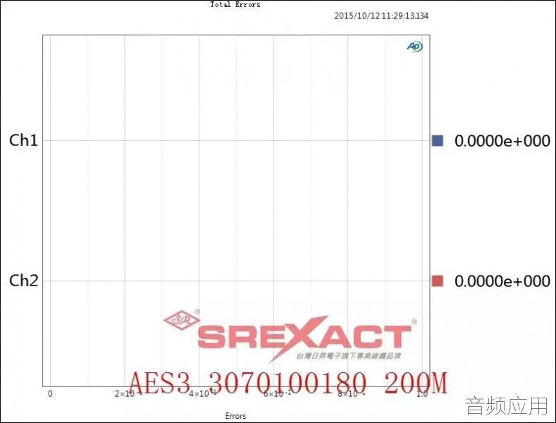
ÕâÒ²¾ÍÊÇΪºÎºÜ¶àAESÏßÀÂΪºÎÔڹǼÜÌî³äÉÏÇãÏòÑ¡ÓÃPEÌõµÄÔÒò
ÀýÈçÎÒ˾3070100180 ¾ÍÊÇΪÁ˸ø´«ÊäÏ߶ԳÅÆð¿Õ¼ä
±ÜÃâÔâÓö¼·Ñ¹Ê±µ¼Ö´óÁ¿µÄËð»µ
×¢4 ÔòÌáÐÑÓû§±ØÐë°ÑÍøÏߵģ¢Ï߶ԣ¢ÓÃÆðÀ´ÓöÔ!
±ê×¼ÖÐÊ×Ñ¡½¨Òé²å½Å4ºÍ5 ´ÎÖ®ÊDzå½Å3ºÍ6
±ê×¼ÖÐÒ²¶ÔÓÚÉ豸¶ËÍø¿Ú½Ó¿ÚÌá³öÁËÒ»¶¨µÄÒªÇó
ÖÁÓÚ×¢5 Ìáµ½UTPµçÀ¿ÉÒÔÖ§³Ö400Ã×µÄÎÞ¾ùºâÆ÷´«Êä
ÕâµãдµÃ±È½Ï²»ÑϽ÷
ºöÂÔÁË:
£±£®Ò»°ãÍøÏßÊÇÖпյĶÔÓڶԽʿØÖÆÊÇȱʡµÄ¿ÉÄܵ¼Ö¶ԽÊËÉ¿ª
£²£®ÍøÏߵĵ¼Ìå´Öϸ¶àÑùÄ¿Ç°CAT5E UTP ÊÐÃæÉÏ´ó¶à··ÂôµÄÊÇ
26AWG ÕâÖÖʹÓÃ0.4mm ÍË¿µÄ²úÆ·½ØÃæ»ý½öµÃ 0.12mm2¶Ô±ÈÔçÆÚµÄ
24AWG ʹÓÃ0.51mm ÍË¿µÄ²úÆ·½ØÃæ»ý0.2mm2
ÕâÒâζ׎ØÃæ»ý¼õÉÙÔì³ÉÁ˵ç×èÉý¸ß Ò²¾ÍÊDzåÈëËðºÄ´ó
Õâ¾Í¿ÉÄܵ¼Ö´«ÊäÄÜÁ¦²»Èç±ê×¼ÉÏËù±ê³ÆµÄ¾àÀë
£¨Í¼Æ¬À´×ÔÓÚÍøÂ磩

C.2 Line driver characteristics
C.2.1 Output impedance
The line driver shall have a balanced output with an internal impedance of 110 ¨´ with a tolerance of 20 %, at
frequencies from 0,1 MHz to 128 times the maximum frame rate when measured at the output terminals.
C.2.2 Signal amplitude
The signal amplitude shall lie between 2 V and 7 V peak-to-peak, when measured across a 110-¦¸ resistor
connected to the output terminals, without any interconnecting cable present.
NOTE a typical value is 4 V ¡À 10 %.
C.3 Line receiver characteristics
C.3.2 Maximum input signals
The receiver shall correctly interpret the data when connected directly to a line driver working between the extreme voltage limits specified in C.2.2.
NOTE The AES3-1985 specification for line driver signal amplitude was 10 V peak to peak
maximum.
C.3.5 Common-mode rejection
There shall be no data errors introduced by the presence of a common-mode signal of up to 7 V peak at frequencies from DC to 20 kHz.
|


 »Ø¸´